|
Phantom Powering:
how it works, do's and don'ts |
Patch Bays
and phantom powering |
Splitters
and phantom powering |
Transformers
and phantom powering |
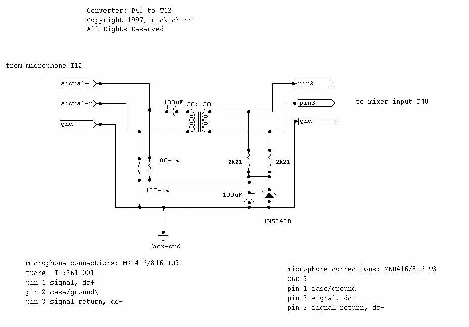
T-Powering | ||||||
|
In the middle of 1965, Schoeps introduced the CMT 200 microphone. An RF condenser design, it was powered by 12v, supplied to the microphone via the mike cable using a phantom circuit. This is the first known usage of a phantom circuit for microphone powering[1]. Sometime around 1970, Neumann introduced the Fet-80 series of condenser microphones that were solid state and remotely powered via the microphone cable. In typical German fashion, they decreed that these microphones were the be-all and end-all to microphones of any sort, and they promptly discontinued all of their vacuum tube microphones. Of course, nearly 40 years later, we know different, with the venerable U47 now selling for the price of a car. Here then, are a series of articles, that explain this important concept and how it works. BTW, Neumann "gave" the idea to the industry; they claim that they trademarked the term, phantom power, and gave the concept and the term to our industry. There! Something for free from Neumann! (But as you can see, Schoeps beat them to the punch, however it was Neumann who standardized the value at 48V.) About that time (1965), another (non-compatible) system for powering condenser microphones via the microphone cable was in use. This system is known as T-System, A-B Powering or Modulation Lead Powering. Phantom powering uses pins 2 and 3 of the XLR for the postitive side of the power supply, and pin 1 of the XLR for the negative side of the supply. T-powering puts the power source across pins 2 and 3, with pin 1 only serving as the shield conductor. |
||||||||||
|
||||||||||
Copyright © 1999-2009 by Rick Chinn. All rights reserved.
Last modified 04/14/2011. 18:27:16