In the late 1970s, ElectroVoice made a series of electret condenser vocal mikes labeled PL76, PL77, 1776, 1777. There may have been others too, but they were all similar, more or less. To make some differences between the models, and maybe to hit a price point, they made the PL76 and 1776 microphones run from a battery. Making matters worse, this was a mercury battery, which is not available any longer.
These aren't bad microphones by themselves, and converting one to P48 powering is fairly simple. Once you do this, battery operation is no longer an option, but since you can't buy the batteries any longer, it doesn't matter.
Click on any image to make it larger.

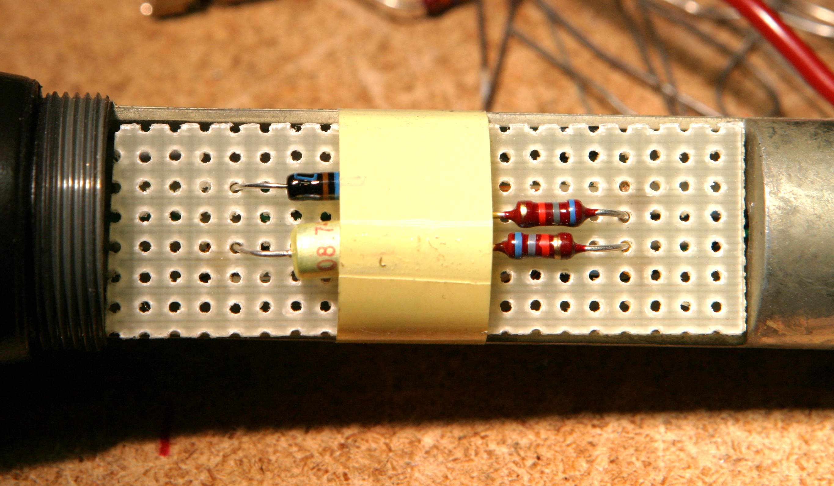
The adaptor board, taped into the battery compartment of the microphone.
- a hunk of Vectorboard (perf board),
- 2ea 6k8 1/4-watt resistors,
- 1ea 5.6v zener diode (1N5232B),
- 1ea 10uf/15v electrolytic capacitor.
Nothing in this circuit is terribly critical. The links to Mouser are just suggestions. The resistors could be 1/8w, The zener diode could be a 250mW part, or it could be a 1W part (1N number will be different). The electrolytic capacitor is plain vanilla, and the value can deviate (larger is ok, higher voltage is ok), but when it's all done, it has to fit inside the battery compartment.

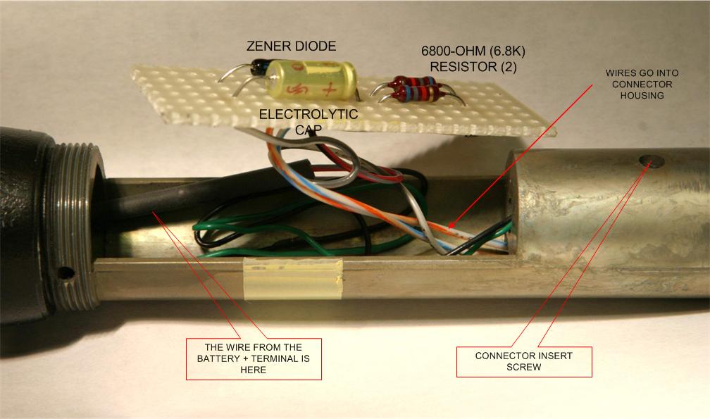
View of the assembled Vectorboard.
 Another view of the assembled Vectorboard.
Construction
Cut a piece of vectorboard that fits across the flats of the battery compartment. Tin snips work just fine. Lacking that, you can score the board by dragging a sharp knife across the perfs several times, then flex the board against the cut marks to encourage it to break along the scoring.Build the circuit on the vectorboard. Fasten with tape. To build a circuit using Vectorboard, push the leads through the board, then bend them flat against the board, bending them to approximate a printed circuit board. Lay the leads of different components across each other and solder.
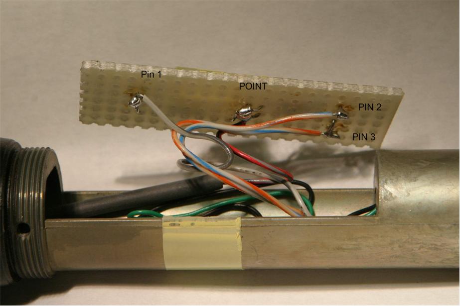
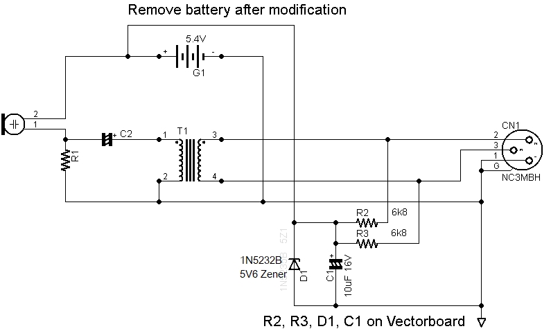
- The 2 6k8 resistors go from pin 2 and pin 3 to a tie-point. one resistor from pin 2 to the point, one from pin 3 to the tie-point.
- From the point, the zener goes to pin 1 (cathode/bar of zener to tie-point).
- The lytic goes across the zener, + of cap to bar of diode.
- The tie-point goes to the + battery contact. Just solder the wire to the battery contact. You're never going to put another battery in there anyway.
- I taped the board into the battery compartment.
To get inside the microphone, unscrew the battery cover part of the body.
You'll need to access the connector. Locate the connector's locking screw at the end of the microphone. Turn the screw counterclockwise to loosen it. This is a Switchcraft insert, so the screw retracts INSIDE the connector, and you can now grab one of the pins with a pair of pliers and gently pull it loose (lest you break the wires attached to it). Now you can solder the wires going to the vectorboard to pins 1, 2, and 3. Then thread the wires back into the battery compartment and reinsert the connector insert. Remember to lock the connector in place by turning the insert screw clockwise.
Now you can solder the wires to the connection points on the vectorboard.

Schematic Diagram. Parts with no values are part of original microphone.
The schematic may show D1, the zener as 1N5235B, 5V1. It should be 1N5232B, 5V6.