All About Pads
A question that pops up frequently is that of building attenuator pads. Here is what you need to know, in one place.
What is a Pad? Where can I use them?
A pad is nothing more than a network made of resistors that creates
loss (attenuation) in a transmission line. Pads can be designed with
many different attributes: matched impedances, unmatched impedances,
etc. You might use a pad to reduce the level of a +4dBu source to
-10dBu, or to allow a microphone preamp to handle the signal from a hot
microphone in front of a loud source (even with the preamp's gain trim
control at minimum, it still clips).
A thorough treatment of the subject can be found in the following
(among others) references:
- The Audio Cyclopedia, 2nd ed., Howard W. Tremaine
- Handbook for Sound Engineers, the New Audio Cyclopedia, Glenn Ballou
- Motion Picture Sound Engineering, Research Council of the Academy of Motion Picture Arts and Sciences
- Sound System Engineering, Davis & Davis
All of these texts deal with the subject from the classic
matched-impedance standpoint; where the line is driven from a specific
impedance, and terminated by that same impedance. These are power-based
transmission systems. The concept is that maximum power transfer occurs
when the load impedance matches the source impedance.
Today, most audio systems operate on the voltage transmission model.
Sources have low impedances, and loads are many times this impedance so
that they bridge the source. You can model the connection of source and
load as a voltage divider. Looking at it this way, you can see that the
majority of the source voltage appears across the load, and only a
small fraction is lost in the resistance representing the source
impedance.
The usual application for a pad is to attenuate the output of a
microphone that is too high for the dynamic range of the following
microphone preamp. Using a matched-impedance pad here is not optimum
(this is not to say that it won't work) because even microphones expect
to have their output bridged by the input impedance of the microphone
preamp.
Another issue here is one of coloration. The microphone and preamp
operate together as a system. The input impedance of the preamp (which
is not resistive) varies with frequency and this interracts in a
complex manner with the output impedance of the microphone (also not
resistive). If there are transformers involved at either end, that's
just an additional factor in the equation. This complex interraction
causes coloration, which may be good or bad, beneficial or harmful.
It's one of the things that make different preamps and microphones
sound different. The point here is that you can minimize the change in
coloration caused by inserting a pad by paying attention to this detail
and designing the pad to mimic the conditions present before its
insertion. The easiest parameter to mimic, and the one that is the biggest contributor
is the impedance that the pad presents to the microphone, and the source impedance
that it presents to the microphone preamp.
Configurations
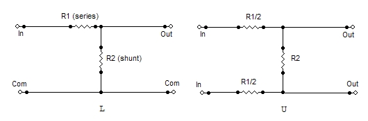
Although there are many different configurations (L, T, bridged-T,
etc,), they all boil down to a form of a voltage divider. Two resistors
in series, with the input across both, and the output across one. The
resistor at the input is in series with the output; the resistor at the
output is in shunt. The output voltage is divided by a factor equal to
1 plus the ratio of the resistor values (ignoring source and load
impedances). You can
prove this for yourself
using Ohms law, and then
comparing this result with that obtained by using the resistor ratios.
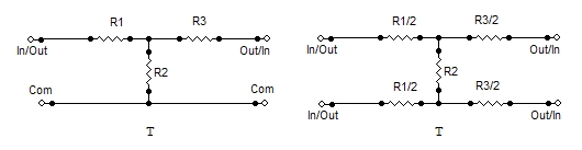
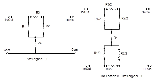
All of these configurations may be made into balanced configurations by
simply mirroring them. For example, a balanced T-pad (known as an H
pad) has resistors in series with both sides of the input, and both
sides of the output, but with a common resistor (R2) bridging the
midpoints of the series legs. The series resistors are half the value
used for the unbalanced case. In the following diagrams, the notation R1/2 means
"the value of R1 (in the unbalanced case) divided by 2."
| Unbalanced
|
Balanced
|
Remarks
|
|
Match input or output but not both.
Asymetrical. Input and output can not be exchanged.
|
|
Symetrical. Input and output can be exchanged.
|
|
Symetrical. Input and output can be exchanged.
R1 = R2 = line impedance
|
These configurations may be made adjustable by making the various
resistances variable. The non-trivial part is that the resistances have
to change according to a particular relationship which is not linear.
To get an adjustable T-pad, you must buy it as such. An adjustable
L-pad has 2 variable elements, whereas an adjustable T-pad has three.
The Bridged-T pad is popular because two of the resistors (R1, R2) are
fixed and never change value (they are always equal to the pad
impedance), so making this configuration adjustable is just a matter of
making R3 and R4 variable. It is possible to buy a ready-made pot that can be used as
a bridged-tee attenuator but they are expensive and subject to minimum order quantities, making them nearly impossible to purchase. It is easier to make a bridged tee attenuator using
a rotary switch but this also makes the attenuation steps discrete.
Values
Now there's the matter of values. You can compute these using a
spreadsheet (like Excel), or you can use a scientific calculator. If
you only have a four-banger (that's add, subtract, multiply, divide for
you newbies), then you'll need to go find an ancient textbook with a
log table at the back. You can also use a table of K-factors.
The formulae for finding the resistor values needed for the T and
Bridged-T configurations can be found in any of the
references mentioned at the beginning of this document. Since these configurations are most often used in
impedance-matched systems, they don't concern us beyond basic
familiarization. For the purposes of this page, we'll concentrate on
the L-pad, U-pad and O-pad.
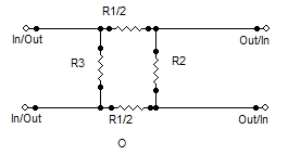
As mentioned before, the L-pad is the classic voltage divider circuit
using two resistors to reduce the input voltage by some amount. Both
the U and O configurations are derived from this (if you're a little
circuit savvy, you've probably already figured this out). For example,
to convert an L to a U pad, you divide the series arm (R1) by two, and
these become the new series elements for the U-pad. Taking this
further, you get to the O configuration only when the pad input
impedance is significantly higher than the impedance bridged across the
output (i.e. the following mike preamp). The extra resistor simply
shunts down the input impedance to better approximate what the
microphone sees with the pad connected to what it sees without the pad.
There are still subtle differences, such as any reactive elements
present at the preamp input, and these will not be mirrored by the pad.
I'll show you how to find the resistor values for any arbitrary value
of attenuation for an L-pad, U-pad, and O-pad. Then, I'll put a
few of the usual suspects into a table. The math involved is not complex; if you have a calculator I invite you to follow along.
Example 1
First, a little setup: We need a microphone pad to attenuate the output
of a high-output microphone that is close-miking a loud instrument. The
microphone is a 150-ohm device, and the preamp presents a 1500-ohm
load. We want to lose 20 dB in the pad. We'll use either a U or O
configuration.
- Convert 20dB to a ratio. The formula is: k = 10^(db/20). That's 10 to the power (db/20). The calculator says 10. 20 dB is a ratio of 10:1. If you have a table of
K
factors, you'll find this value in the column with
K
at the top.
- To achieve this value of loss, the resistors that make up the voltage divider need to have values
that fulfill this relationship: k = 1 + (Rseries/Rshunt). But where do
you start? There are a jillion values you could start with, but the one
that makes sense is the shunt resistor, which effectively sets the
value of the output impedance.
So, Rshunt = Zout = 150 ohms (the microphone imedance).
- Using algebra, manipulate the formula to solve for Rseries when we know Rshunt and k.
Rseries = Rshunt * (k - 1). Since k = 10, k - 1 = 9. In the
K
factor table, there is a column for the value
K
- 1.
- Continuing, Rseries = Rshunt * 9 = 1350 ohms.
- Since this is a U-pad, for a balanced system, we split the series arm into two equal parts. 1350 / 2 = 675 ohms.
- Resistors only come in particular values, so you need to convert these calculated values into standard ones. For 5% tolerance resistors, there
are 24 values per decade (a decade of values is a range of 10:1, the
first two digits are the same, and they get multiplied by factors of 10
to get the higher values). For 1% resistors, there are 96 values per
decade. We'll use 5% resistors here. 150-ohms is a standard value, and
680-ohms is the nearest standard value.
- Summarizing: get 2 680-ohm 5% resistors and 1 150-ohm 5% resistor. Connect as shown in the diagram for a U-pad (balanced-L). If you want to use 1% resistors for
improved common mode rejection (CMR) and maybe sonics, the nearest 1% values are 681 ohms and
150 ohms.
Excel spreadsheet creates K-Factor table.
Practically speaking, the absolute loss is determined by the parallel
combination of the shunt resistor and the input impedance of the mike
preamp. Since the preamp bridges the shunt resistor, the actual loss is
slightly greater than calculated (less than 1dB). For loss values less
than 20 dB, you may have to raise the value of the shunt resistor to
make the series resistors large enough to not excessively load the
source. In that case, the contribution of the preamp's input impedance
to the attenuation error will increase.
Another matter is the impedance seen by the microphone. This is the U
vs O question. Since the mike is connected across all three resistors,
it sees an impedance of (680 + 680 + 150) 1510 ohms. Close enough. For
higher loss ratios, you can add a shunt resistor (R4) across the input
to lower the input impedance to something closer to the mike preamp's
input impedance. Calculate the shunt resistor by finding the resistance
needed to parallel the pad's input impedance to come close to the mike
preamp's impedance.
Example 2
Find the values for the 30 dB pad using the table. The pad input
impedance is 4550 ohms (verify this for yourself). What do we need to
parallel this with to get 1500 ohms? This additional parallel resistor
is R4 in the diagram.
Use a variation of the parallel resistor formula: Rtotal =
1/((1/R1)+(1/R2)). Solving for R1 we get 1/((1/Rtotal)-(1/R2)). The
calculator says 2238 ohms. 2200-ohms is the closest 5% value.
Parts Selection and Construction
To minimize the effect on CMR, you should use 1% resistors, but
common-ordinary 5% carbon film resistors will work. It's definitely not
a case of audio vs no-audio. Wattage is unimportant. For microphone pad
applications, 1/4 watt or less is fine. If you're using this
information for loudspeaker pads (as in a crossover network), then the
resistors need to be able to withstand the amplifier output power.
As mentioned previously, resistors are only available in particular
values (unless you happen to own a resistor factory). The easiest way
to find the standard values is to consult a catalog, such as the
Digikey
catalog. A computer
program
(PC only, not mac) is also available (freeware) to help make this selection.
Of course, for some things, you need to be
right on.
For this, you may need to use multiple resistors in series or parallel to
build the value needed.
The Universal Pad Circuit Board
Uneeda Audio now
has a small printed circuit board
available that accomodates any of
the following configurations: L, T, Bridged-Tee, U, O, H, Balanced Bridged-Tee.
The board is available as a kit, or you can order it pre-configured to a specific
impedance and attenuation value. The board creates a pad with a single value of
attenuation.
Universal Pad PCB
DIY
For pads that operate at line level, you can just build it onto a piece of Vectorboard
or use a terminal strip or terminal board.
NEW
Uneeda Audio now has circuit boards that fit the Switchcraft XLR tube. Please inquire.
The easiest enclosure for a mike pad is an XLR Tube. Switchcraft makes
such a tube, the part number is S3FM (www.mouser.com, p/n 502-S3FM). Build the
pad off of the male
connector pins, with R2 connected across pins 2 and 3, and R1 and R3 flying
in the breeze. R1 should be conencted to pin 2 of the male connector,
and R3 should be connected to pin 3. Keep the wires short, because
there's not much room once things are assembled. Trim the unconnected
ends of R1 and R3 short (1/4"), and then solder some light-gauge (24
AWG) stranded wire to them.
It's helpful to have two different colors so that you can keep pin 2
and pin 3 separate (to maintain polarity through your pad). Solder a
third wire to pin 1 of the male connector, and trim all three so that
they would stick out about an inch beyond the end of the shell of the
tube when the male connector is inserted into the tube. Before final
assembly, strip and tin the ends of the wires. Now insert the male
connector into the tube, leaving the wires sticking out of the female
end. Tighten the setscrew on the male insert. Now solder the three
wires sticking out to pins 1, 2, and 3. Ensure that the wire connected
to R1 ends up at pin 2 at the female end, and that R1 connects to pin 2
at the male end. If you're using R4, connect it across pins 2 and 3 of
the female connector. BTW, the female end is the input.
Phantom Power Issues
In use, it is technically better to connect the pad between the output of the phantom
power network and the preamp input, so the resistors from the pad aren't between the phantom source
and the microphone. If your condenser microphones don't
require much current (like the Neumann Fet80-series), or if they have a wide operating voltage range (like the AKG C-451)
then this consideration is strictly academic. My
advice is to try it before worrying about it.
Formulas
Here, in one place, are the basic formulas for a voltage divider, the basis of the L and U pads. Formulas for
the other configurations can be found in my
Universal Pad Board
manual.
Matched and Terminated systems.
For matched/terminated systems, you need to use the
classic configurations
(H, T, bridged T, etc.) and a
k-factor
table.
Have Attenuation, Need Pad
Given a bridging system, and an attenuation value, calculate the pad resistor values.
-
Get the K factor.
K = attenuation ratio - 1.
attenuation ratio = 10^(dB/20) : read: 10 to the power (db/20)
- Decide if the input impedance or output impedance is more important. Generally, the output impedance is more important for a microphone pad.
For line to mic pads, or line to line, the input impedance is probably more important, because the source must drive it as a load.
-
Output Impedance is more important.
Pick that value. That is the shunt resistor of the divider. The output is taken across this resistor.
Multiply the value of the shunt resistor by K. Convert to nearest standard value. That is the value of the series resistor.
-
Input Impedance is more important.
Pick that value. Presumably you picked a standard resistor value. This is the series leg of the divider.
Divide the value of the series leg resistor by K. Convert to nearest standard value. That is the value of the shunt resistor. The output is taken across
this resistor.
n.b. These formulas will get you close. Usually, getting the attenuation within 0.1dB of some arbitrary value isn't as important as
just getting some value of attenuation that is
close
to what you need. Getting the attenuation value within a gnat's ass of some arbitrary value requires taking into consideration the actual source and load
impedances.
Have Pad, Need Attenuation
Given a bridging system, and given a random voltage divider, derive the attenuation.
- Get the divider ratio by dividing the series leg value by the shunt leg value.
- Convert this to K by adding 1.
- Convert K to dB either by looking it up in a k-factor table, or by calculating:
dB = 20 * log(k) : read dB equals 20 times the log of K.
n.b.
The log function used here is the base10 log, where log(2) = 0.30102
n.b. Again, this will get you fairly close to the actual attenuation value. Getting more exact numbers requires taking into consideration the
source and load impedances.
The Promised Table
| Microphone Pad Values (U or O)
|
| dB loss
|
k
|
R1
|
R2
|
R3
|
R4
|
Config
|
Remarks
|
| 10
|
3.16
|
510
|
470
|
510
|
|
U
|
Impedance values are a compromise.
|
| 11.79
|
3.88
|
10k
|
3.6k
|
|
|
L
|
+4dBu -> -10dBV pad
Values for line level operation. Use L-pad schematic. (Unbalanced)
|
| 15
|
5.62
|
510
|
220
|
510
|
|
U
|
Impedance values are a compromise.
|
| 20
|
10
|
680
|
150
|
680
|
|
U
|
|
| 25
|
17.78
|
1300
|
150
|
1300
|
3300
|
O
|
|
| 30
|
31.62
|
2200
|
150
|
2200
|
2200
|
O
|
|
| 40
|
100
|
7500
|
150
|
7500
|
|
U
|
Use to convert line level to mike level; i.e. use a mike input as a line input.
|
| Note:
K is the voltage loss ratio for the pad. The resistors for the L and U configs follow the ratio K-1.
|
Links
Universal Pad PCB
The documentation for this product has formulas for calculating other configurations.
Discussion/explanation of the
standard values
used for electronic components, and a computer program to convert from ideal to standard values.
Design Service
If you can't make heads or tails out of the calculations, I'm happy to do them for you...
For a Price.
Design time is $100 per hour. Most designs take 15-minutes. The design process is
supposed to be simple, so this should be a learning experience for you. Whatever... Send
me your problem, and its application, and I'll tell you how many 15-minute blocks this represents.
If you order the pad board kits from me, calculating the resistor values is included in the price. (within reason, my interpretation).
Of course, you're welcome to do it yourself.
Copyright © 2001, 2002, 2003, 2004, 2006, and 2024 by Rick Chinn. All rights reserved.
typo correction 2024.
Last modified 01/03/2024 22:00:30.

 soldered across pin 2 and pin 3 of the male connector.")
 now soldered in.")


